Now, there are a number of containers running on my cluster which make use of Tailscale in one way or another. I have my Tor proxy there, which is published as a service using the Tailscale k8s operator. I keep a dedicated exit node in a pod, which is also handled for me by the operator. And there are some that use Tailscale directly: (golink, idp, etc.)
But using these isn’t as efficient as it could be. Because when you try to use them, traffic always starts out going via one of the off-site DERPs for a while until the hole-punching sorts itself out. After all, one of the points of k8s is that the internal pod and service networks are separate from your physical network, and not routable from it:
❯ tailscale ping idp
pong from idp (100.93.174.43) via DERP(dfw) in 34ms
pong from idp (100.93.174.43) via DERP(dfw) in 99ms
pong from idp (100.93.174.43) via DERP(dfw) in 28ms
pong from idp (100.93.174.43) via DERP(dfw) in 26ms
pong from idp (100.93.174.43) via 172.16.0.129:16232 in 1ms
So I started thinking about how to optimize this, and it occurs to me: we have peer relays now. And how hard could it be to put one of those inside a pod with access both to the host and the pod networks?
As it turns out, not very hard at all, but harder than it should be.
This file contains hidden or bidirectional Unicode text that may be interpreted or compiled differently than what appears below. To review, open the file in an editor that reveals hidden Unicode characters.
Learn more about bidirectional Unicode characters
If you’re going to try and replicate this, note that I’ve put it in the kube-public namespace where I keep all the things that intermediate between the cluster and the outside world; and that you will need to change the MetalLB annotations to suit whatever load balancer and local network addressing scheme you have.
Also, this isn’t quite all of it.
You can configure Tailscale to be a peer relay using the tailscale set command after it’s running, but you can’t use the relevant —relay-server-port and —relay-server-static-endpoint options with tailscale up. Ordinarily I’d put a script in a custom container to do this sort of thing, but since at the moment I’m experimenting - and since we’re letting Tailscale store its state in a secret, it will persist past pod restarts - I just kubectl exec-ed into the tailscale-peer-relay pod once it was up and ran:
tailscale set --relay-server-port=61441 --relay-server-static-endpoints=”[fdc9:b01a:9d26:0:2::3]:81441,172.16.2.3:61441”
Again, if you’re doing this yourself, change the endpoints to the same ones you used for the service.
How does it look now?
❯ tailscale ping darkweb-tor
pong from darkweb-tor (100.65.32.54) via DERP(dfw) in 26ms
pong from darkweb-tor (100.65.32.54) via peer-relay(172.16.2.3:61441:vni:57) in 2ms
pong from darkweb-tor (100.65.32.54) via peer-relay(172.16.2.3:61441:vni:57) in 2ms
pong from darkweb-tor (100.65.32.54) via peer-relay(172.16.2.3:61441:vni:57) in 1ms
pong from darkweb-tor (100.65.32.54) via peer-relay(172.16.2.3:61441:vni:57) in 3ms
pong from darkweb-tor (100.65.32.54) via 172.16.0.130:23828 in 2ms
Much better! Everything but the first packet in the ping stays local, saving a good 100 ms of route-establishment.
Now, if I could just figure out a way to eliminate that first requirement to hit an external DERP at all, that’d be perfect. But this is a start.
In which article I do a quick deep dive into what exactly the $30 (max spindle speed) setting in Grbl, the Cubiko and other CNC routers’ firmware, actually means, as applied to spindles and to lasers.
(If you stick around to the end, I’ll also tell you why you shouldn’t cargo-cult the setting of it when you switch to the laser module.)
How Do You Control The Speed Of An Electric Motor, Anyway?
Therein lies the question.
Fundamentally, the answer is that you control the amount of power you put into it. The more current flowing through the motor, the faster it goes1 (the actual speed being determined by where power going in and load being turned meet on the graph).
So how do you control the current? Well, the traditional way of controlling the current is to control the input voltage; according to Ohm’s Law, the current flowing between two points is always directly proportional to the voltage across those two points. The supplied Cubiko spindle motor is a 24V DC motor with a nominal speed of 10,000 rpm; if, instead of 24V you contrive to supply it with 12V, it’ll run at 5,000 rpm instead2.
The problem, though, is that most means of controlling voltage suck.
Back in the stone-knife-and-bearskin days of electronics3, we were more or less limited to putting a resistance in series with the motor. The ratio of that resistance to the resistance of the motor determined how much voltage was experienced across each one, therefore how much current, therefore how much power, and therefore how fast the motor ran. If you used a variable resistance (a rheostat), you could vary the speed of the motor accordingly4.
The problem, as you may have spotted, is that the power is still supplied to the whole thing, and that part of it that isn’t used by the motor is going to be dissipated in the resistance, where it will come out as heat. Apart from being inelegantly wasteful, this means that if you have a 75W spindle motor running at half-speed, that means you would have 37.5W of power turning into heat in the resistance on your driver board, and that’s not going to make the electronics very happy.
(Another issue with this control mechanism, incidentally, is that motors are an inertial load, which to strip it right down to the basics means that it takes more power to start them turning than to keep them turning. This means that if you want to have them run slowly and set your voltage accordingly, they won’t turn at all; they’ll just sit there and act like a resistance, turning power into heat - you have to start them at a fast speed and then slow them down. In many applications, this is rather inconvenient.)
But Obviously We Fixed That, Right?
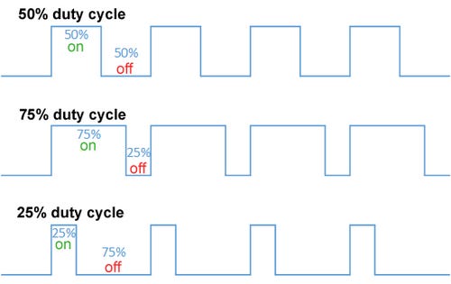
Outside of very cheap products, yes. In the 1940s and 1950s, we invented pulse width modulation. What is pulse width modulation? Well, at its simplest, it’s a way of turning the flow of power on and off very quickly, so that it’s only flowing for a set fraction of the time (the duty cycle).
Illustrative image taken from Wikipedia.
This is a much more efficient way of controlling the current - averaged across time - flowing through the motor, because the switch dissipates almost no power when either fully off (because there’s no current) or fully on (because there’s no voltage across it), unlike a resistance.
And because the motor’s an inertial load, it keeps turning while the power is off, as long as you keep the total cycle length short and switch quickly enough. A DC motor, like the 24V spindle motor, running at a 50% duty cycle, thus behaves in practice just like a 24V spindle motor receiving 12V5, and obligingly runs at half speed.
You can also phrase duty cycle as “effective voltage”, which is the effective voltage the motor is getting averaged over time - for example, if we chop the whole cycle into four, a 50% duty cycle is effectively 24V + 24V + 0V + 0V / 4 = 12V, and a 25% duty cycle likewise 24V + 0V + 0V + 0V / 4 = 6V.
(I dislike this terminology because it obfuscates how PWM works underneath, but it’s generally accepted, so.)
About The Switch…
If you were wondering where the switch is…
You already guessed, didn’t you?
…yes, it’s that MOSFET I talked about in a previous article.
To go into some details that will come in useful later: the microcontroller inside the Cubiko, which runs Grbl and controls the machine, does the actual work of providing a PWM signal at 5V on one of its pins.
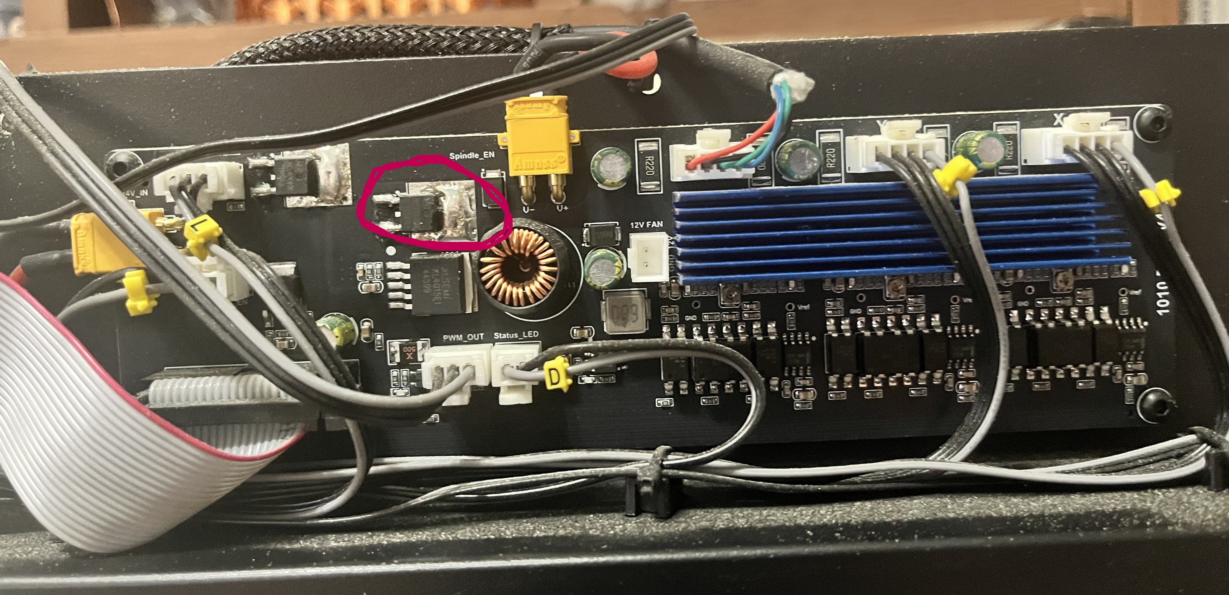
This signal is then sent to two places. It is sent to the laser via its cable (you can see on the picture below the MOSFET a connector labeled “PWM_OUT”) to control it, which I’ll talk about later, and it is send to the circled MOSFET. The MOSFET then acts as a glorified switch, turning the 24V supply to the spindle on and off to match the signal it’s getting from the microcontroller.
And that’s how motor speed is controlled!
Bringing This Home To $30
If you’ve been following along, you may be wondering how it is that we get to set spindle speed in terms of rpm, since nothing on the electronics side of the spindle understands rpm. The answer is, as it so often is, approximations.
What the microcontroller can actually do is set the duty cycle of its PWM pin (and therefore, ultimately, the spindle power) to any of 256 discrete values6, from completely off (0V, all the time) to completely on (5V, and thus 24V at the spindle, all the time). In terms of “effective voltage”, that translates to 0.02V7 (0.1V at the spindle) increments.
People who do cybernetics for a living will chafe at the notion that we’re really “controlling” the spindle speed, insofar as it depends entirely on approximate fractions of the nominal speed of the spindle motor, and that it will inevitably slow down once placed under load since we don’t actually monitor its speed and vary the power supply to ensure that this doesn’t happen.
And they’re right to do so.
But much like, for example, the way that we don’t actually track the position of the axis steppers on 3D printers and low-end CNC machines but rather rely on dead reckoning, we’ve found that these approximations work well enough 99% of the time, and thus only the people who really need them should bother paying for the associated sensors and significantly more complex motor control circuits/algorithms.
Grbl has the job of transforming the spindle speed commands you send it into these 256 values. What $30 (maximum spindle speed) and $31 (minimum spindle speed) do is define a range of rpms which will be mapped onto a range of duty cycles, from completely on, to “lowest possible”8, 0 always being completely off.
So if you set $30 to 10000, such as it is for the default Cubiko spindle, requests for spindle speeds work out like this:
S10000 is 1.0 of $30; 1.0 of 255 is 255; 255/255 of 24V is 24V effective; 24V is 10,000 rpm nominal9
S9000 is 0.9 of $30; 0.9 of 255 is 229; 229/255 of 24V is 21.5V effective; 21.5V is 8,958 rpm nominal
S5000 is 0.5 of $30; 0.5 of 255 is 127; 127/255 of 24V is 11.9V effective; 11.9V is 4,958 rpm nominal
S2500 is 0.25 of $30; 0.25 of 255 is 63; 63/255 of 24V is 5.9V effective; 5.9V is 2,458 rpm nominal
S1000 is 0.1 of $30; 0.1 of 255 is 25; 25/255 of 24V is 2.3V effective; 2.3V is 958 rpm nominal
S0 is 0.0 of $30; 0.0 of 255 is 0; 0/255 of 24V is 0V effective; 0V is 0 rpm
The first thing you should note is that the numbers at the end are approximations of what you asked for. This is because there are only 255 gradations between $31 and $30, meaning that the smallest change in rpm the driver supports is $30/255 = 39.2 rpm. Essentially, the spindle speed space is divided up into bands 39.2 rpm across, and you’re going to get the speed of the band you land in, not the exact number you asked for.
The second thing you should note is that since the spindle speed you asked for goes through a process of being converted to voltage and back again via a series of mappings and approximations, it doesn’t necessarily have to map the “right” way.
The Land Of Really Bad Ideas
So what happens if you install the optional 20k spindle?
Well, if you’re smart, you set $30=20000, and then all the spindle speeds in your gcode still make sense.
Now S20000 means 24V rather than S10000, and the rpm “bands” are now 78.4 rpm wide instead of 39.2 rpm making your requests a little more approximate, but by and large, everything works the way you expect.
But what if you don’t? What if you leave $30 at 10000? What happens then?
…nothing, so far as the firmware is concerned. It doesn’t know that you’ve swapped out the spindle motor. But as the nominal speed of the new motor is 20,000 rpm at 24V instead of 10,000 rpm, your spindle will turn twice as fast as your gcode tells it to.
This may lead to broken bits, messed-up workpieces, and other assorted consequences, but the firmware won’t care. You’re just asking it to supply a given voltage and it’s doing that.
Can you do this intentionally? Sure, if you change all the spindle speeds in your gcode and in the design software that writes your gcode and in your head to reflect the twice-as-fast reality. You could also set $30 to 1000 with the regular spindle and treat all your numbers as 1/10th of what they should be, or set it to 255 and treat it as raw voltage increments.
Should you? Hell no. I’m only telling you this so you have a better understanding of what’s going on under the covers, and an easier time figuring out what went wrong if you accidentally forget to change $30.
So How Does This Work For Lasers?
Laser power is controlled by PWM, just like motor power.
This is actually more important for lasers than motors, since unlike motors, lasers work well at one voltage and can’t simply have their output power changed by varying the input voltage10. The simplest way you can control how much lasing you get is PWM: actually turning the laser off part of the time.
Conveniently, the drive board in the Cubiko already has a PWM circuit to run the spindle, so it takes the PWM signal from the microcontroller before it reaches the spindle MOSFET and uses that to tell the laser when to switch on and off. That’s what the third wire in the laser cable is for.
Now where the laser is concerned, forget all those “effective voltage” notions. Laser power is expressed simply in terms of the duty cycle. At 100% (i.e., on all the time), you’re getting the full power of the laser. 50% laser power means 50% duty cycle, halving the power-delivered-per-second. 25%, 10%, 1%, 0.25%, same principle. It’s still limited to the 256 different settings that Grbl and the microcontroller can deliver, so your laser power setting will be rounded into the nearest 0.4% band.
And This Interacts With The Spindle Settings How?
Because you use S-commands to set the laser power, just like you use them to set the spindle speed. They already exist, so we re-use them.
So when you have the laser installed, the numbers between $31 and $30 map onto the space between 0% and 100% for laser power. So, if you don’t change the default at all from the $30=10000 that the Cubiko’s configured for by default for its standard spindle, you get 100% laser power by sending S10000, 50% by sending S5000, 0.25% by sending S25, and so on.
In practice, though, you won’t see this because your laser software conveniently asks you for laser power in percentage terms. So how does it know what to ask for?
Yep. It maps laser power percentages to spindle speed requests so the firmware can map them back to duty cycle percentages and timings that the drive board can deliver to the laser, and if this sounds Rube Goldberg to you, you’re absolutely right to think so. It’s just that all these components were built by different people in different places and times, so occasionally things are less perfectly integrated that we, looking at them now, might prefer.
But to do this mapping, the laser software and the Cubiko firmware have to agree on what spindle speed represents 100% laser power.
Setting $30 For The Laser
The standard advice given is that when you install the laser module, you should - in addition to setting laser mode ($32=1)11 - set $30=1000.
This is not strictly correct. It will be correct much of the time because there’s a lot of laser software out there that defaults to using permille laser power in its S-commands, but what you actually need to ensure is that the software you’re using to generate and send gcode, and the Cubiko, have the same understanding of what $30 is.
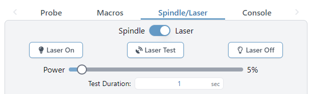
To pick one example, I use gSender to send the gcode for my milling jobs. In gSender, there is this control here which lets you select between spindle and laser mode:
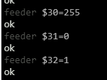
When you flip the switch to “Laser”, as you can see in the console tab, it sends the following commands:
…meaning that 100% laser power is set with S255, and any gcode I was going to send to the laser using it - especially if it uses anything but full power - needs to be compiled accordingly.
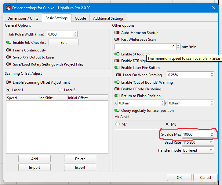
What I actually use for laser work is LightBurn, and LightBurn lets you configure it to match the Cubiko, rather than the other way around. If you go into Device Settings in LightBurn, you’ll see this option:
…”S-value Max”. What you need to do is set this to match the $30 value on your Cubiko, and LightBurn will generate its laser power S-commands to match. I have set it to 10000, as this way I don’t have to remember to change $3012 when I swap spindle for laser or vice versa.
To sum up: for the laser, it’s that they match that matters, not the absolute value. Find out how your software does it, and configure it and/or the Cubiko accordingly.
And That’s It
I hope you enjoyed, or at least found informative, this little trip down through the innard of motor and laser control on the Cubiko, and other similar machines. See you again next time!
This is obviously a huge simplification that applies as written to direct current motors, such as the Cubiko’s spindle motor, and not to either alternating current motors or stepper motors. Go with me here.
I can’t think of a reason offhand why you would set $31 to anything other than zero on the Cubiko or anything using a conventional DC motor, but if you do, any spindle speed between zero and $31 will get the lowest output, 0.02V effective, and the range between $31 and $30 will be mapped as above.
If you’re like me, you will instantly be asking “So what if I ask for a faster speed than $30?” The answer is: nothing more than if you had asked for $30. You can’t get more than everything, so you’ll take the full voltage available and like it, young man.
The reasons for this involve the energy levels of the electrons doing the lasing and quantum mechanics. I’m not a trained physicist, just a well-educated layman, but I could still ramble on about how this works for many paragraphs - but this post is long enough already, and doesn’t even have a margin.
This is very important, because what it does is turn off the pause between motion commands that change the spindle speed. (This pause exists because a spindle takes time to accelerate, and so not pausing for a moment to allow it to do so results in trying to cut with the spindle at the wrong speed or even stopped, which is a good way to break a bit. The laser, on the other hand, can start firing at full power immediately, so pausing with the laser installed means you get burned spots or possibly even fires.)
I’ve seen more than a few people confused about how exactly Z-probing works on the Cubiko and what it does, so I thought I’d write this article to explain the procedure hopefully a little more clearly than the manual does.
And to clarify, this means that I’m not talking about height mapping (the procedure that measures the flatness of your stock, so you can engrave with extra precision - usually only relevant if you’re making PCBs), or platform calibration (the one-time procedure you do to calibrate your platform against the probe button1). Those are more complex procedures which require the leveling cable and more time, and are only done when you need them.
I’m talking about using the Z-probe to set up your workspace, which you’ll do every time you run a new job on your Cubiko. Fortunately, it doesn’t need the cable or anything else, and while I’ve taken a lot of time for explanations in this article, once you’re used to it will take you a couple of minutes, max.
So here we go, talking about the regular Z-probe, the one which is used to set your Z0 - which in part of the origin of your workspace coordinates (i.e., the ones which define how the bit moves against your stock), and in most cases is the precise location of the top of the stock you intend to mill.
This means that our first step is to measure the height of the stock, because we need to tell the printer how far above the bed (i.e., the probe depth) its top is.
To digress for a moment, I have heard a few people wondering why this isn’t as simple a Z-probe process as that found on 3D printers. Well, there’s a reason for that, and it all comes down to the difference between an additive and a subtractive process.
Both the 3D printer and the CNC machine need to bring two objects into precise alignment in order to work properly. For the former, it’s the bed and the nozzle; for the latter, it’s your stock and bit.
But for the 3D printer, the two have the advantage that they usually do not move relative to each other (their commanded movement notwithstanding). If you have a modern 3D printer where they sorted this all out at the factory, the measurements of the offset between the probe and the nozzle were arranged at the design stage and compiled into the firmware, and the initial Z-offset was measured and set before it was shipped to you, and so you can home your 3D printer and be assured everything will end up in the right place.
Unless you modify your hot-end and move the probe relative to the nozzle, or change out the nozzle or the bed and therefore alter their separation - in which case you get to have a fun time micro-jogging the Z-axis up and down while trying to feel for exactly the right amount of friction on your piece of paper2.
Anyway, the point is that the CNC machine is always in this situation. You will use differently sized stocks, so your “bed” will not always be at the same height - and even nominally identical pieces of wood are never quite identical, or flat, to the requisite level of precision - and your “nozzles”, the bits you use, are not all the same length, nor do you insert them the same distance every time. Meaning, in essence, that you have to do the equivalent of the Z-offset calibration every time you run a job on your CNC.
Fortunately, the probe makes it easy! But you can’t get away without measuring something.
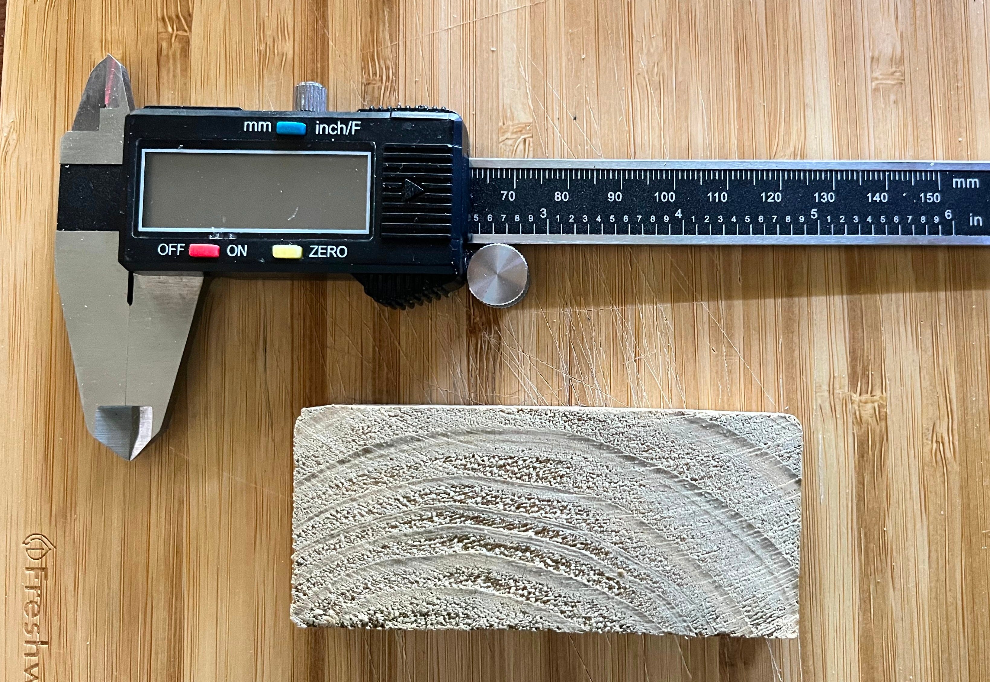
First, take your stock before you fasten it down - it being much easier to measure things you can hold in your hand - and whip out your handy-dandy digital calipers.
The stock I am using for today’s job, along with said handy-dandy digital calipers.
You don’t have to use digital calipers, of course. But they give nice and accurate results, and you’re going to be measuring an awful lot of things in your CNCing career, so I would probably be remiss at this point if I didn’t tell you that you’re probably going to want some sooner rather than later. (These are mine.)
If you’re a Fusion user, like me, setting up the manufacturing job will want all the measurements of the stock, so go ahead and measure the X and Y dimensions too at this point. But if your CAM process doesn’t need those, that’s okay.
We need to get the height of the material along Z for the next part of the process, but, as I mentioned before, wood has the unfortunate property of rarely being perfectly even. If there’s an obvious high spot, you can measure it there; what I do, when there isn’t, is take one measurement at each corner to allow for cutting-angle defects. On the piece above, they came out as 12.47, 12.01, 12.02, and 12.21 mm, respectively; on the basis of this, I take the highest measurement and, for my convenience and to allow a certain degree of measurement error, I round it up to 12.5 mm.
This will inevitably lead to a little bit of air-cutting or thin-layer cutting at the start of the job. Remember, a little bit of air-cutting isn’t a sin; it’s a protection against unexpectedly deep cuts.
…don’t forget to add its thickness to the total material height that you enter into the Cubiko. This is because the probe process can’t know that you have a spoilboard on the bed, so you need to account for that yourself. (But, obviously, don’t add the thickness of the spoilboard to the stock height that you enter into Fusion or your other CAM software, because you don’t intend to cut into it.)
I have a 2.5 mm thick PLA spoilboard, which makes my material height for probing 12.5+2.5=15 mm.
Go ahead and secure the stock to your spoilboard/bed at this point. As you’ll see in later pictures I’m using carpenter’s tape for this, but whatever floats your boat.
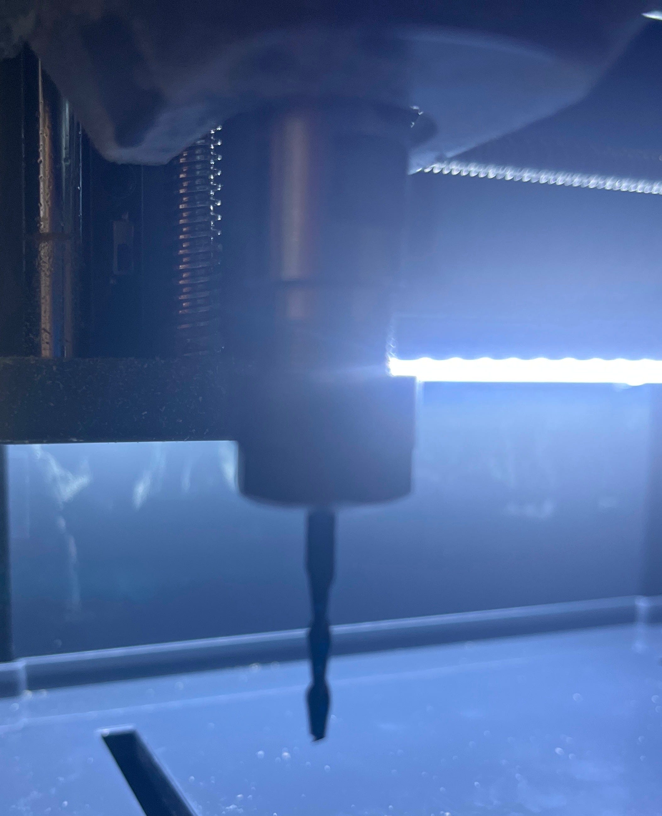
Then install the first bit you’re going to be using. The important thing to keep in mind here is that there must be enough bit available below the collet (no less than 15 mm regardless of how short the bit is4) to push the probe button. So, something like this:
Bit’s in the spindle with plenty of room…
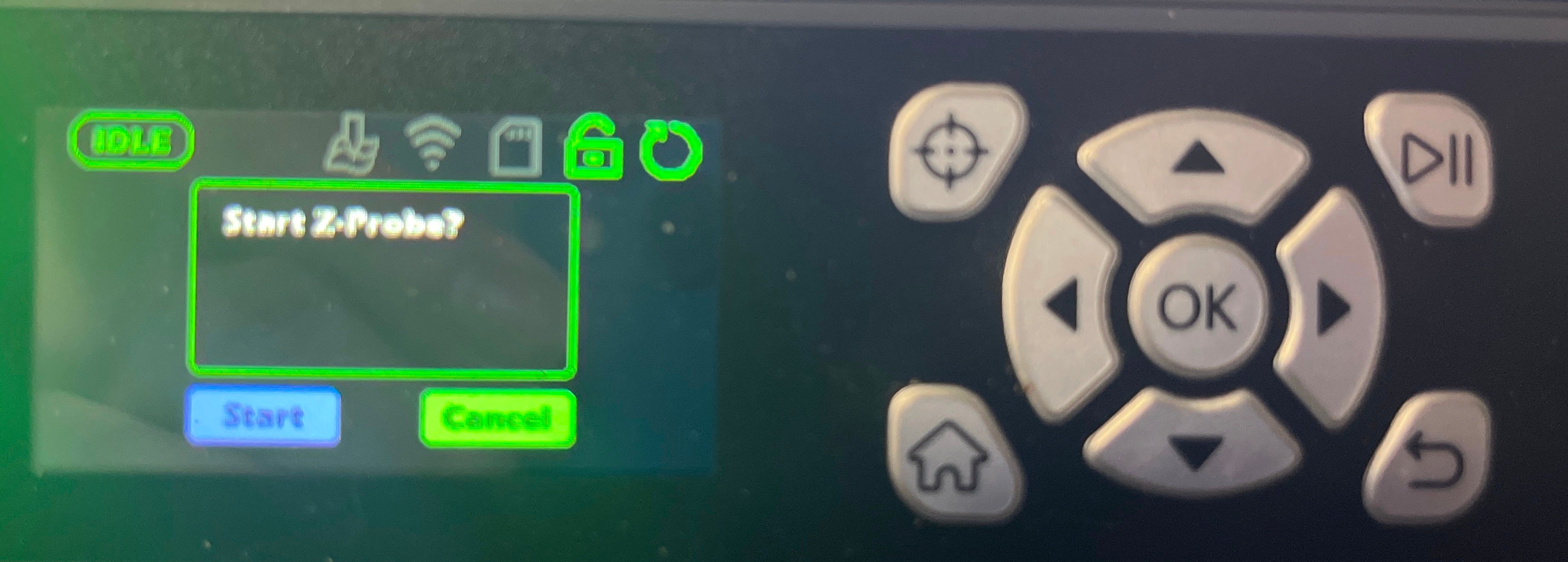
And at this point, we can go ahead and do the probe. You start it by pushing the top-left button on the Cubiko’s controller5; the one with the target symbol on it in the picture. That will bring up this screen:
Start Z-Probe?
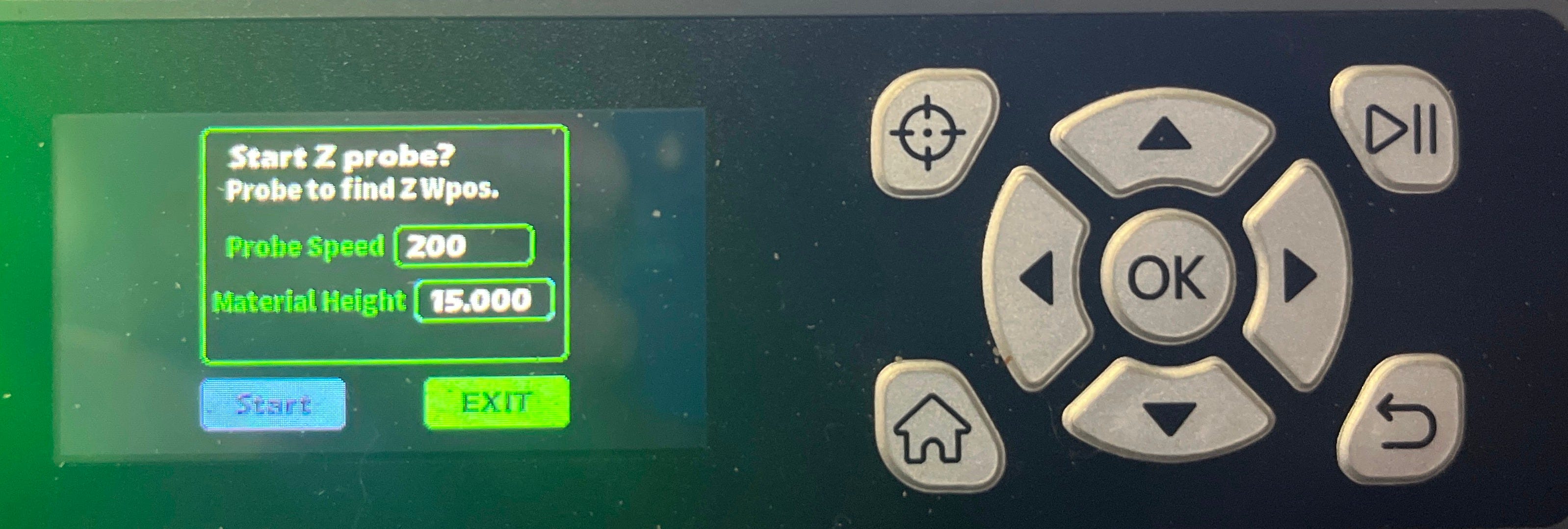
Hit OK to start the probe. This will bring up a second screen which asks for parameters:
Probe to find Z Wpos.
Leave the probe speed alone, but change the material height to the one you calculated earlier (in this case, 15 mm). Then go ahead, select Start, and hit OK. The probe routine will now run.
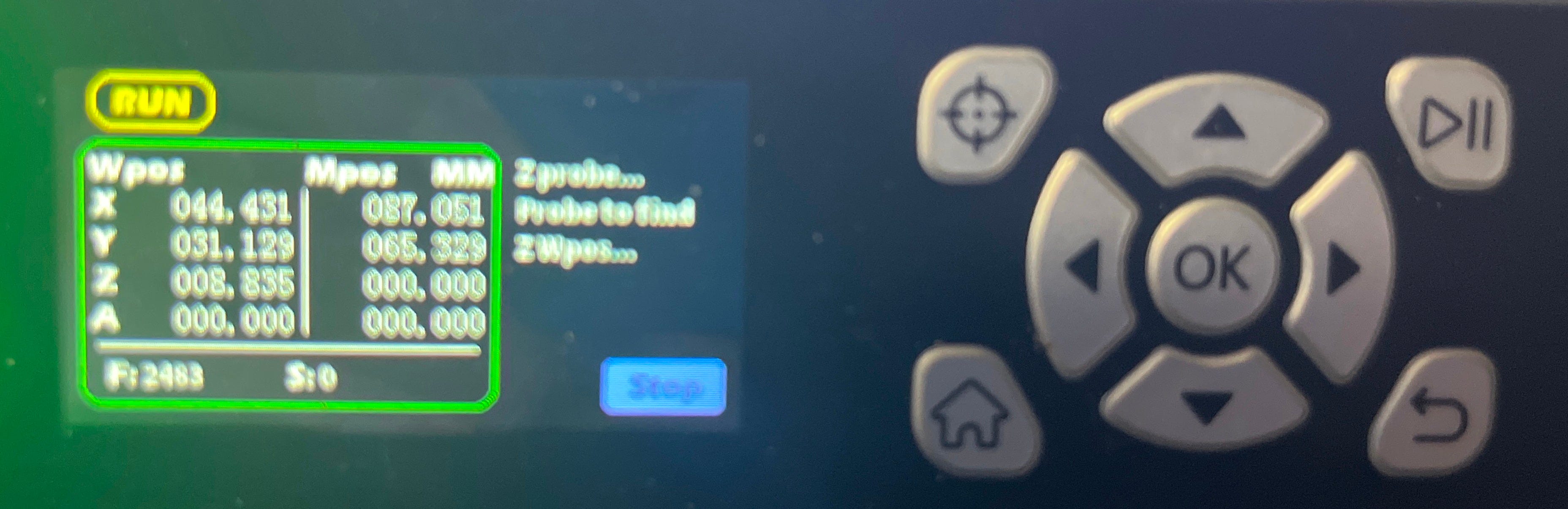
It looks like this.
The machine will first home, then move so that the bit is over the probe button. It’ll dip the spindle twice to push the button, and finally move to the probed Z-height (i.e., just above the stock, if you did your calculations right). When the controller goes back to the home screen (a second or so after the spindle stops moving), the probe routine is done.
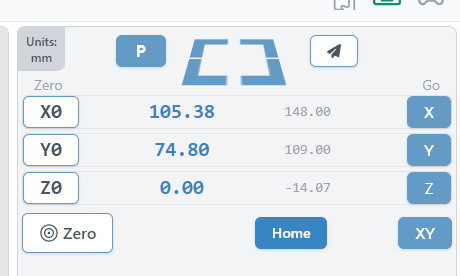
If you have your computer hooked up and your gcode sender running during all this, at the end of the probe routine, you should see something like this (this is gSender):
The coordinates display in gSender.
In gSender, the larger blue numbers on the left are the workspace coordinates, and the smaller grey ones on the right are the machine coordinates. As you would expect at this point, the workspace Z coordinate is 0, indicating that you’re all set up on that axis.
Now, it’s time to zero in X and Y. You should be able to do this by jogging with your gcode sender (or on the Cubiko controller). Be sure to leave the Z axis alone while you’re doing it - and while you’re moving onto the stock, or above it, go slowly. It’s always possible that there’s some raised bit on there that wasn’t obvious, so if you find the bit dragging on the stock as you move it (leaving little trails behind it, or the spindle being turned by the movement), go back and do the probe again adding another 0.2 mm to the height.
If that doesn’t happen, and it usually won’t, go ahead and move the bit to the starting position and hit the buttons to zero in the X and Y axes.
And now you’re done!
It should look like this.
How do I change bits?
Of course, you’ve got both a roughing and a finishing pass to run, if not multiple finishing passes, some engraving, some drilling, etc., and they all need different bits. Do you have to do all this again every time?
No!
(At least presuming your software, like Fusion, uses the same workplace coordinates for each pass. Which it should, really, because it makes life so much easier.)
Just change the bit between passes, and then repeat the probe procedure without changing the material height. That will put the tip of the new bit at the same Z-height as the tip of the old bit, and, importantly, the probe procedure doesn’t change the X- or Y- zeroing you did yourself. Which means your subsequent passes will run just as they should.
Any questions?
Feel free to ask them in the comments, or over on the Genmitsu Cubiko Launch Group on Facebook. I’ll answer as best I can.
Amusingly enough: the default? 0.475 mm. The results from my platform calibration? 0.473 mm. That’s twenty microns difference, folks, smaller than the thickness of a human hair and roughly the height of two bacteria standing on each other’s pseudopodia. I think we can feel pretty good about the factory calibration, here.
This usually comes up with relatively short bits like the V-bits supplied with the Cubiko. It’s not a problem you’re going to run into with bits like my heavily used Ø2.5/15 mm flat end mill.
It may in the future be possible to do this procedure from your controlling PC or the phone app, but so far I haven’t found a way to. The Z-probe procedure available in the Genmitsu app is designed for their other CNC machines with different Z-probes, and unless you hook up the cable and configure the Cubiko to behave like those machines, it will run the bit right into the bed.
(Many thanks go to Jan Roubal and Johnmichael Quinlan from the Genmitsu Cubiko Launch Group on Facebook for assistance received in solving the problems described, and thus indirectly in writing this article.)
Not because they are easy, but because they’re easier than the alternative.
Enough of this.
So, I’ve still been having fun making things with the Genmitsu Cubiko, and that fun continued right up until last Monday, when after one short milling job (around 45 minutes), the spindle didn’t stop running. Despite Gcode stop commands and the emergency stop button, and even powering off the machine only stopped it while the power was off. It started right up again when power was reapplied.
In short, I had a dead MOSFET.
The MOSFET in question (circled in red). Also note the other MOSFET to its left and above, and the 12V FAN connector in the middle of the picture. We’ll get back to them later.
If you don’t know what a MOSFET is, it’s the circled widget in the picture above. It’s a transistor used to control the power supply to the spindle motor (which as you can see is plugged into the yellow XT30 connector just to the right of the circled MOSFET), and thus both whether it spins at all, in which direction, and how fast.
Unfortunately, when it gets too hot, it can fail, and when it fails, it fails “open”, meaning that power flows and the spindle just keeps running.
(I will mention at this point that, despite some suspicions, I don’t think that this is a design flaw with the Cubiko, mostly because even though it isn’t actively cooled, there’s a heat sink exactly opposite these two MOSFETs between the board and the folded steel chassis of the machine, and my failure was after a very short period of time in cool conditions, after many longer jobs had completed successfully.
In my opinion, it’s much more likely that some of we backers were just unlucky enough to get machines built with a batch of MOSFETs that were flaky from the factory. Good enough to pass QA, but with a temperature tolerance a lot narrower than it should have been. Sometimes bad part weeks just happen.
That being said, yes, I added extra cooling anyway. Belt and braces, belike.)
Here’s what I did, in case it’s of use to any of you with the same problem, or if you want to do any of it preemptively.
Starting the Process
First thing to do, obviously: disassemble the machine to be able to get at the drive board. This is very simple: just follow the process described in this video, courtesy of the manufacturer.
I will, however, tell you to have a whole lot of little trays available before you start, because this process produces a whole lot of screws, and you will need to keep them all sorted, separate, and in places they are not likely to fall off.
When you’re done, the drive board - as seen in the picture above - is the circuit board located running across the upper back of the machine, easily identifiable by having “1010 Drive V4.0” printed on the right-hand side.
I will also recommend at this point taking a photograph of the board, printing it out, and making yourself a neat map of where all the cables go using the handy yellow tags on them, because your next step is going to be carefully disconnecting them all, removing the four screws holding them in, and taking the drive board out, and when you’re done, you’re going to have to put all this back just the way it was before.
As you are removing it, you will have to pry the board (being sure not to bend it) off the heat sink behind the MOSFETs, to which it is attached with thermal tape. Be very careful, because you’re going to want to put it right back on there afterwards.
Don’t touch the control board on the left side of the machine (looking from the rear). You’re not doing anything with that.
The Book of MOSFET
The first thing you need to do, obviously, is remove and replace the failed MOSFET. For a replacement, this one from DigiKey (the IPD082N10N3GATMA1) does the job nicely. You only need one, so naturally I ordered two, just in case I broke one in the process. At $1.60 each (at the time of writing), it’s cheap insurance.
I also, at this time, ordered a couple of these V2016B heatsinks1. These are very small (8.5 mm x 8.5 mm) heatsinks just right for perching on top of a MOSFET for additional cooling, and since additional cooling never hurt anyone, we’re going to add them. You’ll need two of these, since just to the left of the spindle MOSFET, you’ll see another one that’s used to power the whole Cubiko on and off. We’re not replacing that one, but we might as well add some cooling to it just in case.
…I’m not going to tell you how to replace the MOSFET in detail. This is for two reasons - the first being that if you already know how to solder, you don’t need me to tell you, and if you don’t this is not the place to start out; and the second being that since this was my very first time working with surface-mount components, I’m the last person who should be trying to teach anyone else how to do it.
Suffice it to say that with the cunning use of solder wick and my trusty iron, I got the old one off the board and put the new one on with no more trouble than some vaguely irritating flux stains.
Having done this, take some thermal glue (I used this one) - normal glue will not work, since you need good thermal conductivity - put a dab of it on the bottom of the heatsink, and attach it to the top of the MOSFET. Do the same thing for the second heatsink and the power MOSFET we mentioned earlier. Allow forty minutes or so for the glue to dry enough to be secure, and you can put the board back in.
Hol(e)y Case, Batman!
Now, I could have stopped there.
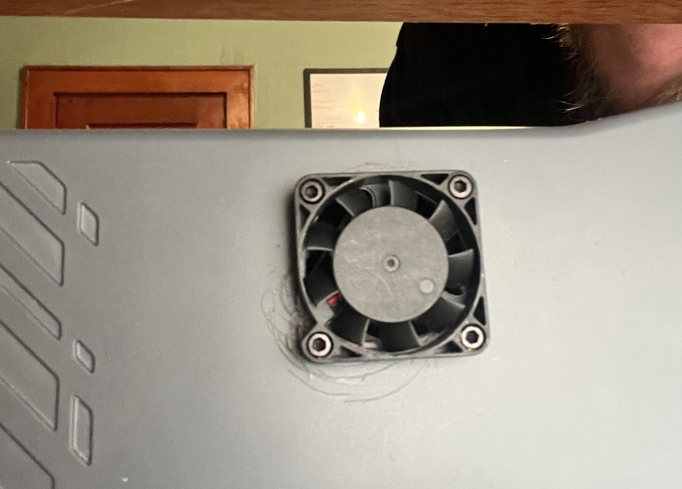
But as it happened, I had a box of 12V 40mm fans (these ones) left lying around from earlier upgrades of a 3D printer2, so why not, I thought, add some active cooling? Especially since there’s a perfectly good 12V fan connector on the drive board currently going entirely unused3.
The first step in doing this is to make a place to mount it on the back of the case, which requires you to make some decisions. My first one was the most obvious: while many cooling fans function as exhaust fans, I decided to set up my Cubiko fan to blow air into the case. I chose this because, new hole aside, the other obvious air path out of the drive board compartment is the cable path over the top of the steel frame which leads to the working area of the machine, and it’s obviously better to have air moving in the direction that keeps dust and chips out of the electronics, rather than the one which draws them in.
(On the fans I had, this just involved taking the cable out of the existing strain relief and adding a drop of glue on the other side to take its place.)
I also decided to mount the fan on the outside of the existing case, rather than the inside. There was probably room in there for it, but it’s already crowded, so why make my job any harder than it needed to be?
You’re aiming for just left of midline, at the top of the upper part of the case. Drill from the outside4, or you won’t get it high enough.
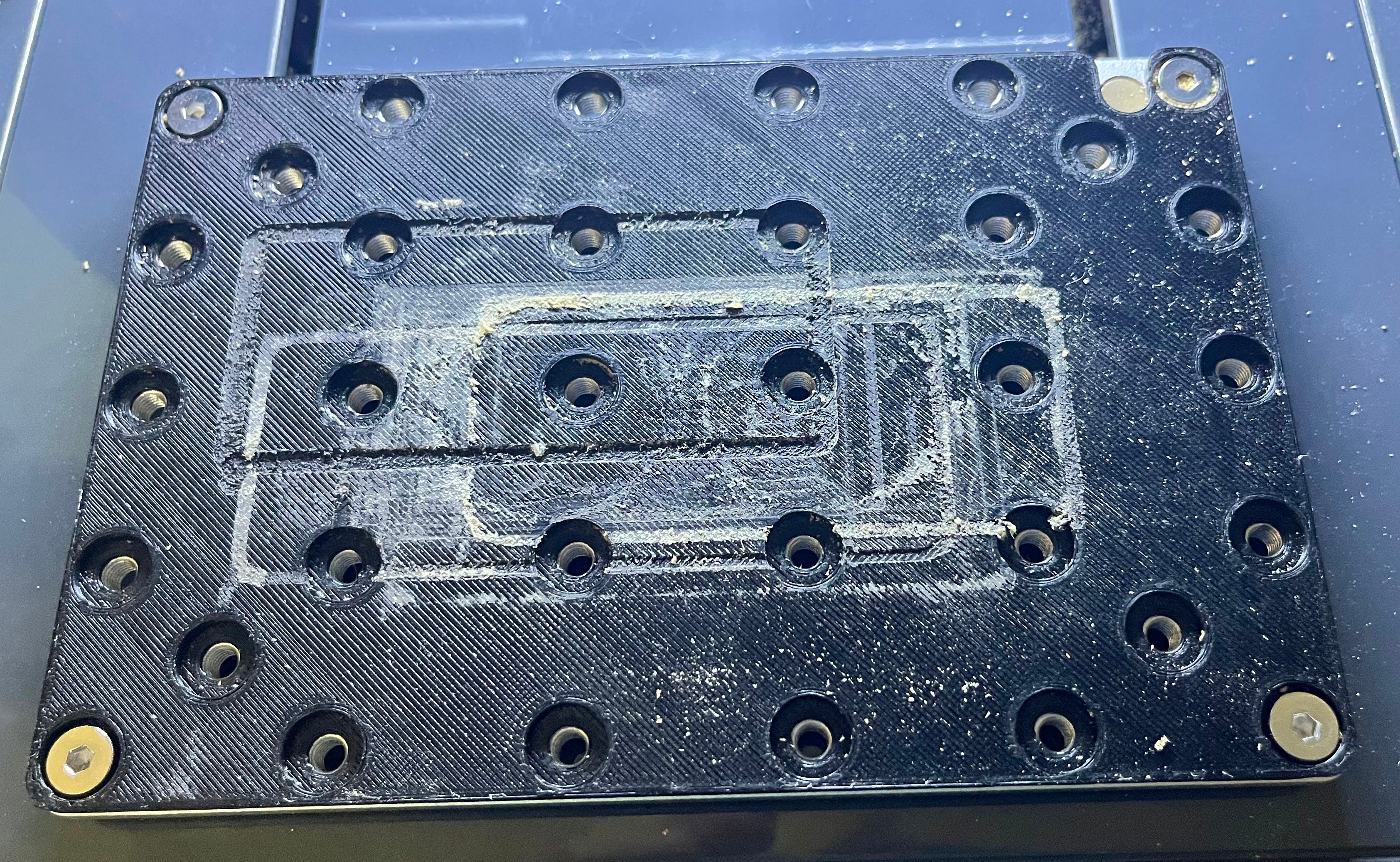
Kind of a mess, isn’t it?
Don’t do what I did and try to use a hole-cutting bit to make your fan hole unless you are much better at it than me, since it will skip messily, promises of working well on “hard plastic” aside, and make a mess of your case. I ended up drilling a ring of holes with my screw-hole bit and using a Dremel to join them up and finish it off.
This also isn’t quite done; I’m going to 3D print a clip-on protective cover for the fan that will coincidentally also cover up the scratches.
Then just plug it in as you reassemble. Even a small (40 mm) fan like mine should provide a very satisfying flow of air out of the existing air hole in the back of the case when operating with the cover on.
And We’re Done
Test it’s all working, and then reassemble the machine. Preferably in that order, as taking it apart and putting it back together is kind of a pain.
And now you’ve fixed your MOSFET problem, and/or ensured that you won’t have a future MOSFET problem.
These are $0.48 each (at the time of writing), but there is a $0.12 tariff each on importing these pinkie-nail-sized chunks of aluminium. And that’s all I’m going to say about that.
If you’re not buying new fans, and even if you are, make sure you check the voltage. A lot of current 3D printers use 24V fans these days, and there are also lots of 5V fans out there.
Make sure you also check the polarity of the fan wiring against that of this connector. My fans had plugs wired backwards vis-a-vis the board socket, so just plugging them in caused them to (a) not run and (b) get hot, which is the opposite of what you want. I had to cut and resplice the fan cable with the wires swapped over.
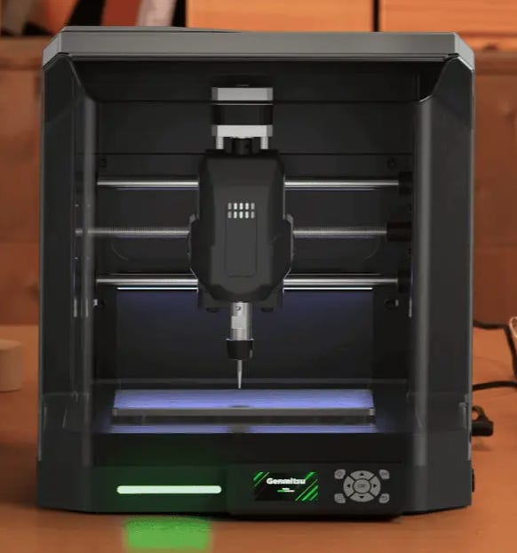
So, as those of you who follow me elsewhere may know, I’ve been getting into CNC recently, with the help of this sweet little desktop machine:
The Genmitsu Cubiko, from SainSmart via Kickstarter. And since it has arrived here, I’ve been having a merry old time designing little widgets in Fusion 360 and milling them out of assorted bits of scrap lumber hereabouts as I learn and practice on my way to larger projects.
As of yesterday, however, the laser module I got along with the machine in the Kickstarter arrived, so I’ve been getting started with some laser engraving. This module, as it turns out, is the already-existing Genmitsu CFL55-33 laser module, a nice 5.5W violet diode laser that works very nicely indeed.
But for one eensy issue.
Connecting it up and configuring it (using LightBurn for now, at least) was simple, as was using it. But where physical installation is concerned - well, the Cubiko uses a 42 mm spindle, which you take out and replace with the laser module. There are four corners neatly cut into the otherwise circular interior of the spindle clamp to let you do just this. But unfortunately, it turns out that in practice - at least on mine - when you put the laser in the spindle clamp and tighten its bolt as far as it will go, the laser (at 33 mm each side) is just too small to stay fixed. Close enough that it will stay where you put it, even, but that’s not quite tight enough for me to trust it when it’s moving back and forth at laser-engraving speeds.
At first I was able to shim it with a thin piece of wood I had handy, and move on. Which worked fine for my initial runs, but isn’t what you might call a permanent solution.
So I turned to 3D printing for a solution, but printing a round holder for the laser was out: a 33 mm square won’t fit into a 44.5 mm (the interior diameter of the clamp) circle, period. So instead I experimented by making a thin, square belt for the laser, to slip on over it and clamp down.
That worked, but even a very thin “belt” - one that came out on the printer as a single wall, and that alone - was too much. While it would hold the laser in place, it bowed out between the corners in use, and also placed what I deemed to be excessive strain on the clamp.
Which led me to my eventual solution.
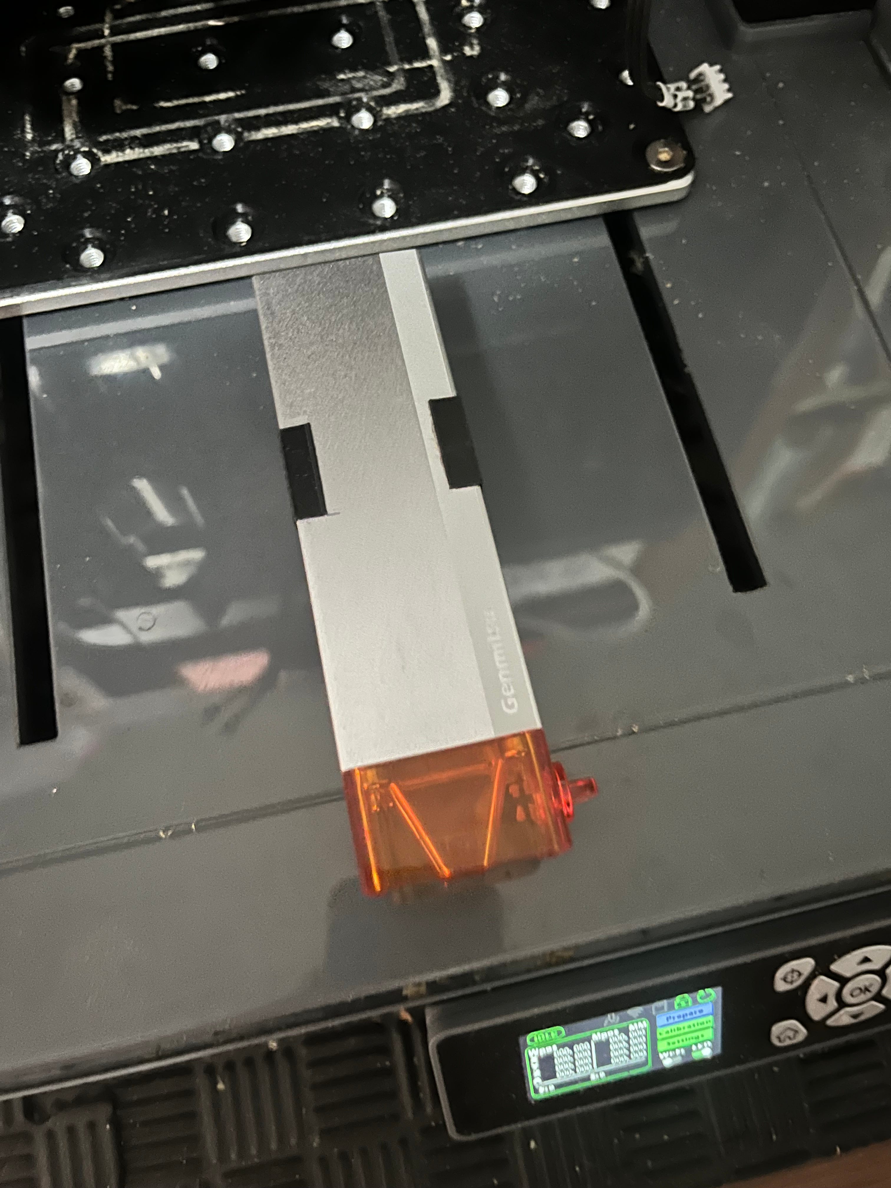
This, if you will, is a laser wearing suspenders.
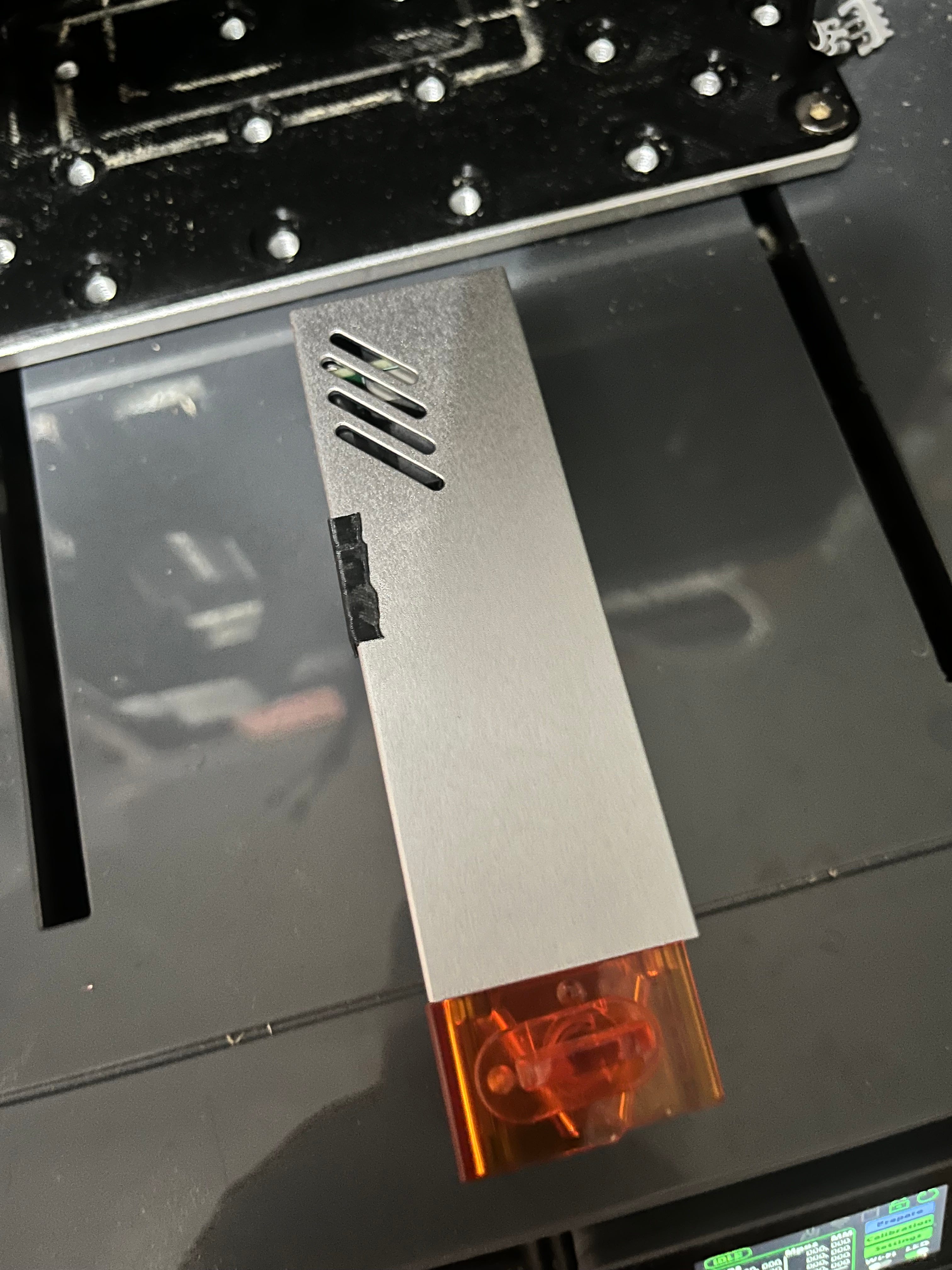
My eventual 3D print job (which you can download here as the .STL to print, or here as the original Fusion archive) consists of two small right-angled “suspenders”, each one printed wall thick, which widen the laser for 18 mm of its height at the appropriate spot, just enough to let the spindle clamp grip tightly.
To make sure I installed them at the right spot (just below the vents, as seen in the below picture), I used the following procedure:
Dialed the laser in, while placed in the clamp, for a job on very thin material. For me, this meant positioning the Z axis at -38 mm (machine coordinates), and positioning the laser thereafter with the built-in focus widget on a 2 mm wood blank over my spoilboard.
Using a thin Sharpie, make a small mark on each side of the laser where it emerges from the bottom of the spindle clamp.
After removing the laser, place a drop or two of cyanoacrylate adhesive on the inside of each “suspender”, and apply them to the front corners of the laser as seen in these pictures, lining up the bottom of the suspender with your mark.
Let the cyanoacrylate cure. I don’t recommend putting the laser back in the clamp until it does.
As long as you’re installing it at a height where the “suspenders” are within the clamp, from now on, your laser should fasten there securely.
You’ll note that by setting the default position for them where I did - i.e., dialing in the laser on very thin material - there’s plenty of room to adjust the position of the laser for different jobs - there’s only a small distance further down you can go before reaching the bed, and with 18 mm of “suspender” inside the clamp in the original position, there’ll still be plenty available to hold the laser in position.
Going up, you’ve got 18 mm in which you can raise the laser inside the spindle clamp before the top of the “suspender” reaches the top of the clamp, not to mention a whole 38 mm of Z axis to play with.